
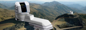
On a mountain top in Chile, the world’s largest digital camera will be installed to survey the southern sky. The Large Synoptic Survey Telescope (LSST) will one day be able to scan the sky “almost from horizon to horizon” according to Martin Nordby, Chief Mechanical Officer for the LSST digital camera.
Located at SLAC National Accelerator Laboratory a federally funded lab collaborating on this project, the purpose of the LSST digital camera isn’t only to observe the sky, but also to photograph it, every other night, and tile the pictures together to study how dark energy and dark matter interacts with visible objects such as stars. The effort at the Rubin Observatory is being called the Legacy Survey of Space and Time.
SLAC is responsible for designing and fabricating the digital camera for the LSST, which is intended to stay in one place, unlike other telescope cameras which are typically plug-and-play units that can be swapped out with other instruments.
The SLAC researchers have spent more than ten years designing and engineering a complex, 3.2 gigapixel digital camera capable of capturing what the LSST will see-the camera’s shutter, focal plane made of charge-coupled device (CCD) sensors, cryostat (for cooling) and a filter changing system, among others. Surrounding these subsystems will be an even larger aluminum structure, forming a complete camera weighing 2,800 kg. These large pieces, both approximately 1.65 meters in diameter demanded tolerances within about 50 microns in critical areas to support the high-precision demands of the camera’s operation.
To manufacture the camera housing and back flange, they contracted Keller Technology Corporation in Buffalo, New York, a fifth-generation family-run business known for its expertise in welding and stress relief processes. The shop prides itself on its ability to handle challenging, difficult, and tricky parts. “I like to tell new people that everything here is here because other companies would struggle to do the work” said Scott Steggs, Keller’s CAD/CAM Manufacturing Engineer.
The back flange is a flat, cylindrical part that provides structural support for the rest of the camera and serves as the mechanical interface between the camera and telescope. Made from a 6061 aluminum forging, the part was subject to vibratory stress relief before any machining to stabilize the atoms in the metal.
One of Keller Technology’s specialties is the manufacture of vacuum chambers, typically made from aluminum, that involve the use of welding, machining and polishing capabilities. And although the camera parts share characteristics with the vacuum chambers and other large welded pieces Keller commonly manufacturers, there were some hiccups while machining the camera housing.
The housing is a cylindrical 6061 aluminum part the same diameter as the back flange, but taller (about 2.5 feet high) with thinner walls. The housing is welded together; the main shell is rolled metal, with forged rings on the top and bottom. Additional side plates are welded in several places, as are gussets all the way around the inside.
 For both the flange and housing, Keller used a high-speed head, which features an HSK 100 spindle interface and offers up to 20,000 rpm. The head’s small size allows it to fit inside these large parts to machine difficult-to-reach areas such as the pockets in the back flange. Shrink-fit tooling supported the long tools necessary to reach some of the pockets, and Keller milled with a very light depth of cut to ensure good surface finishes in these areas. The shrink-fit tooling also reduced vibration, resulting in more accurate and smooth cutting.
To program the camera parts for the Parpas machining center, Keller started with Mastercam. – There are a couple hundred operations on these parts, said Steggs, who programmed both LSST parts for the machining center. “It takes prep time to make sure we’re good out of the gate, and Mastercam is really our first line of defense not just for lights-out, but also successfully completing one-off or first article jobs,” he noted. Once the program is created and initial simulations are run, Steggs moved to Vericut (CGTech) for a comprehensive simulation of the toolpath motion and material removal process, including the guards, spindle, tools, clamps, and fixtures. For complex parts such as the camera housing in which the spindle will need to operate deep within its inner diameter (ID), achieving an accurate simulation is especially important. Keller also found that verifying dimensional accuracy and optimizing the tool paths in advance leads to better finishes on surfaces and edges.
Welding was performed in house. The part was then sent out for initial OD/ID turning on a large vertical turning lathe. The shell, which had a starting thickness of 0.625 inch, needed to be finished down to 0.25 inch or less in some places. Welding causes residual stresses in metal, and as the housing got thinner, those stresses began to show. Keller sent the housing out for a low-temperature thermal treatment, hoping it would help stabilize the welded material, but the housing came back from stress relief out of round.
Once the housing returned from stress relief for the second time, Keller removed the spiders and sent it out for turning. The next steps will be to machine the cutouts and finish it on the Parpas machining center.
Steggs already has a CAM program in progress for the part; one benefit to the Mastercam software is that it allows for offline work so that he can work on the camera-housing part while other parts are running in the machining center. By the time the part came back from turning, a CAM program was ready and verified through the Vericut simulation software.
– Finishing inside the part will be challenging, he said, because the housing requires surfacing to remove stock between 0.125 and 0.1875 of an inch throughout. Keller will again rely on the high-speed machining head, not just for its speed, but also its size. The camera housing will go through polishing and inspection before delivery to SLAC.


